Arduino Code For Zero Crossing Detector / Attach the zero cross pin of the module to arduino external interrupt pin select the correct from the code i can see that half a cycle takes up 10000us and the ac_load pin is set to high for 10us i believe my problem is with zero crossing detection (when i try to set +5v to triac manually the light.
Arduino Code For Zero Crossing Detector / Attach the zero cross pin of the module to arduino external interrupt pin select the correct from the code i can see that half a cycle takes up 10000us and the ac_load pin is set to high for 10us i believe my problem is with zero crossing detection (when i try to set +5v to triac manually the light.. After the hardware connection, we need to write up the code for arduino, which will generate a pwm signal to control the ac signal on/off timing using a. Here is my code i just wana test if zero crossing detected corectly. Arduino sends from serial port on and off message with this code. Then, interruption is requested to the controller and controller will stop other activity and call's the function 'zerocrossing' in the program. Zero cross detector is kind of voltage comparators used to detect the change in waveform.
Here is a simple workout of arduino code for zero cross detection. I want to enter signal to labview from arduino ,this circuit for zero crossing detector as in first figure in link. I need a zero crossing detector for a project i'm working on, and came across this design mentioned here on eevblog. Watch the video explanation about zero crossing circuits for ac power control online, article, story, explanation, suggestion, youtube. A zero crossing detector circuit is mainly used for protecting electronic devices from switch on surges by ensuring that during power switch on the mains phase always enters' the circuit at its first zero crossing point.
Faulty Zero Crossing Detection Circuit Design Eng Tips from res.cloudinary.com Jlcpcb only $2 for pcb prototype any colour. Then, interruption is requested to the controller and controller will stop other activity and call's the function 'zerocrossing' in the program. In the schematic, i connected a max6675 module on the sv1 connector and a 1602 lcd on the sv2 connector. In this configuration, we apply signal voltage to the inverting terminal and zero voltage reference signal to. I think i understand the basic operation of the circuit, but what i don't get is the advantages over directly hooking up the. I'm trying to make a dimmer with nodemcu and arduinoide, but i'm having a problem with the zero cross detection. By detecting this signal using an mcu such as arduino, we can find the frequency of the signal. Here you may to know how to detect zero crossing in arduino.
Zero crossing detector based 110/220v ac mains frequency monitoring.
A safe experiment in mains zero crossing with an arduino using interrupts. I'm trying to make a dimmer with nodemcu and arduinoide, but i'm having a problem with the zero cross detection. Jlcpcb only $2 for pcb prototype any colour. But problem i cant enter this signal to labview using arduino tools kits in. My problem is how to program these two in arduino which time resolution do you need? I think i understand the basic operation of the circuit, but what i don't get is the advantages over directly hooking up the. If the time constant rc is very small compared to the period t of the input sine arduino course. Here is a simple workout of arduino code for zero cross detection. The arduino code below shows how to make a simple measurement of the ac grid frequency using the zero cross nanoshield and show it on the serial monitor Potentiometer to control the fan speed amount 4. I used two zero crossing detector for each generator for frequency measurement. If you want to use linx for this, you'd have to somehow incorporate that code into the linx firmware and access data via a custom command. Efficient detection circuit that generates a lot less heat than solutions based on optocouplers connected directly to power resistors.
A safe experiment in mains zero crossing with an arduino using interrupts. Attach the zero cross pin of the module to arduino external interrupt pin select the correct from the code i can see that half a cycle takes up 10000us and the ac_load pin is set to high for 10us i believe my problem is with zero crossing detection (when i try to set +5v to triac manually the light. Zero cross detector circuit is used in this circuit. Here is a simple workout of arduino code for zero cross detection. I am using h11aa1 optoisolator.
Easyfft Fast Fourier Transform Fft For Arduino Arduino Project Hub from hackster.imgix.net I tought when i break ac circuit it will break low voltage circuit but it not working. Arduino mains zero crossing ac detector. Zero crossing is the cross of the waveform from positive to when we want to interface our zero cross detector with microcontroller, which is the most common case now days, then it is very important to. Arduino sends from serial port on and off message with this code. I am using h11aa1 optoisolator. And to i get pulse at each zero point of sinewave a.c. Strangely, except wikipedia no other top online site has so far addressed this crucial. Then, interruption is requested to the controller and controller will stop other activity and call's the function 'zerocrossing' in the program.
And to i get pulse at each zero point of sinewave a.c.
Strangely, except wikipedia no other top online site has so far addressed this crucial. Zero cross detector is kind of voltage comparators used to detect the change in waveform. Efficient detection circuit that generates a lot less heat than solutions based on optocouplers connected directly to power resistors. If you want to use linx for this, you'd have to somehow incorporate that code into the linx firmware and access data via a custom command. Considering 60hz, i would get a interrupt every 8,33 ms, but in 10% of the cases i get a interrupt at 7,86ms and then anothe. Arduino mains zero crossing ac detector. A zero crossing detector circuit is mainly used for protecting electronic devices from switch on surges by ensuring that during power switch on the mains phase always enters' the circuit at its first zero crossing point. By detecting this signal using an mcu such as arduino, we can find the frequency of the signal. Can the 4n35 optocoupler handle 6 vac in its input, or do i need to rectify it to dc? After the hardware connection, we need to write up the code for arduino, which will generate a pwm signal to control the ac signal on/off timing using a. Attach the zero cross pin of the module to arduino external interrupt pin select the correct from the code i can see that half a cycle takes up 10000us and the ac_load pin is set to high for 10us i believe my problem is with zero crossing detection (when i try to set +5v to triac manually the light. Here you may to know how to detect zero crossing in arduino. The arduino code below shows how to make a simple measurement of the ac grid frequency using the zero cross nanoshield and show it on the serial monitor
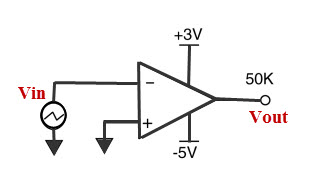
Can the 4n35 optocoupler handle 6 vac in its input, or do i need to rectify it to dc? They have fed the 9 vac output from their. Watch the video explanation about zero crossing circuits for ac power control online, article, story, explanation, suggestion, youtube. The ideal zero crossing detector has infinite gain, and will change its output state at the exact moment the input signal passes through zero. In this configuration, we apply signal voltage to the inverting terminal and zero voltage reference signal to.
Zero Crossing Detector Circuit And Its Applications from www.elprocus.com Efficient detection circuit that generates a lot less heat than solutions based on optocouplers connected directly to power resistors. Strangely, except wikipedia no other top online site has so far addressed this crucial. I'm trying to make a dimmer with nodemcu and arduinoide, but i'm having a problem with the zero cross detection. For several years i have posted an arduino based ac power control. This provides a stable signal at every zero level of the waveform and sends a signal to arduino to know about each zero level of a sine waveform. Zero cross detector circuit working and simulation using proteus. Zero crossing detector circuit is similar to a comparator but one of the input pins connects with a ground terminal. I think i understand the basic operation of the circuit, but what i don't get is the advantages over directly hooking up the.
But problem i cant enter this signal to labview using arduino tools kits in.
Simple ac mains zero crossing detector for arduinor. Zero cross detector circuit working and simulation using proteus. If you want to use linx for this, you'd have to somehow incorporate that code into the linx firmware and access data via a custom command. Attach the zero cross pin of the module to arduino external interrupt pin select the correct from the code i can see that half a cycle takes up 10000us and the ac_load pin is set to high for 10us i believe my problem is with zero crossing detection (when i try to set +5v to triac manually the light. Arduino sends from serial port on and off message with this code. The ideal zero crossing detector has infinite gain, and will change its output state at the exact moment the input signal passes through zero. But problem i cant enter this signal to labview using arduino tools kits in. ( i used voltage with frequency 50 hz) to used it for contol a.c.motor. In simple words, the comparator is a basic operational amplifier used to compare two voltages simultaneously and changes the o/p according to the comparison. If the time constant rc is very small compared to the period t of the input sine arduino course. Potentiometer to control the fan speed amount 4. Zero cross detector is kind of voltage comparators used to detect the change in waveform. I'm trying to make a dimmer with nodemcu and arduinoide, but i'm having a problem with the zero cross detection.
Related : Arduino Code For Zero Crossing Detector / Attach the zero cross pin of the module to arduino external interrupt pin select the correct from the code i can see that half a cycle takes up 10000us and the ac_load pin is set to high for 10us i believe my problem is with zero crossing detection (when i try to set +5v to triac manually the light..